Piecing Together A Sundial
On a recent trip to visit the family down south, my father and I spent some time with my great aunt and uncle. Great Uncle Allan is the reason I'm interested in old engines and machinery, and it was he who started me off with a mostly-restored 2HP Sundial.
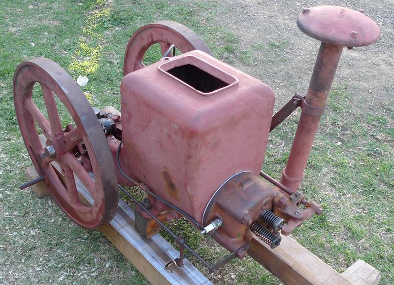
On this visit, we set ourselves the task of restoring a 4HP Sundial which had been lying fallow for a couple of decades. The body and crankshaft/flywheel assembly had been under some tin in the lay-down paddock, painted inside and out with pink rust inhibitor and the rest of the parts were in a number of old 20L paint buckets spread across several sheds.
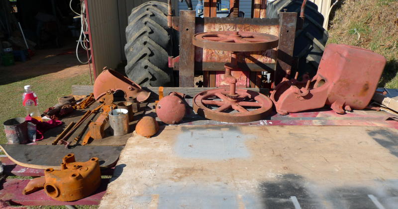
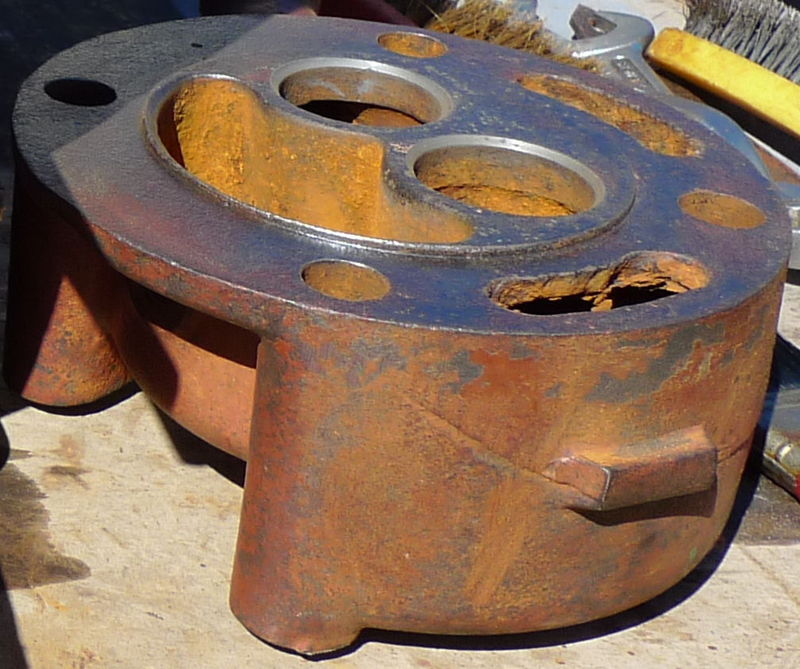
The weather was cool and sunny, so we set ourselves up in front of one of the sheds. The photo to the right shows all the parts laid out. Some water must have got into one of the buckets at one point because some parts including the head, cylinder support and pushrods were bright orange.
The surface rust brushed right off the head, and the valve guides were in reasonable condition. The seats were another matter, with pitting all around. The valves were a little rough too, and lightly re-faced on a B&D valve grinder. The seats were re-faced and then lapped by hand.
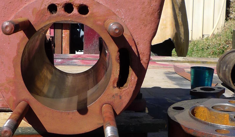
The rust inhibitor on the inside of the cylinder was roughly sanded back and then a hone was used to bring the surface back to an acceptable finish. The inhibitor did it's job very well over the years, with no evidence of further corrosion.
We decided to mount the engine on rails before moving any further, so two lengths of 100mm square pine were cut, marked and drilled. Fortunately, we remembered to measure the fuel tank which sits between them before drilling.
The piston and rings were in excellent condition, though the gudgeon pin was very tight. A little elbow grease soon had it pivoting freely, the rings were installed and the assembly lightly oiled and squeezed into the cylinder.
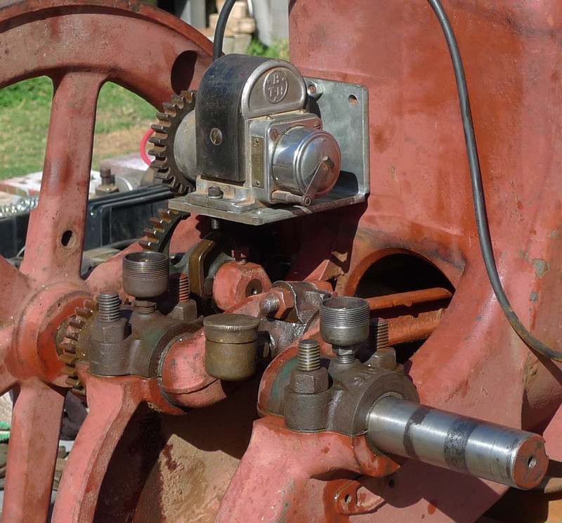
Being a conventional 4-stroke engine, one side of the crankshaft has a gear/cam assembly which drives both the magneto and exhaust pushrod. The gear/cam runs on an idler shaft which is held in a socket in the casting by a setscrew. The two sides of the shaft are not concentric so the cam gear's meshing with the crankshaft gear may be adjusted. The outside end of the shaft has an oil cup with an internal passage to the running surface.
As the crankshaft and flywheels were still assembled, we didn't want to disassemble them if we didn't have to. Unfortunately, paint had penetrated between the crankshaft and the governor sleeve. We attempted to free the sleeve with heat, WD40 and light swearing, but eventually a prybar managed to break away one side of the guide slot for about 1/4 of the circumference.
We now needed to remove the flywheel in order to repair the sleeve, but on the bright side that would also allow us to remove the sleeve without damage. I mean, without more damage.
The whole assembly was rolled over to the big vice and mounted securely. We then spent an hour or so slowly heating up the flywheel and hammering a drift behind the key's head. Eventually the key let go and a gear puller eased the flywheel off the shaft, followed by the sleeve.
The sleeve is made of a more granular or crystalline cast iron then the rest of the engine, and this caused problems when we tried brazing the two pieces back together. Flux would not wet the surface and each of different rods we tried just made isolated blobs. After several hours (and rods), we managed to get several blobs to stick. Certainly not a proper job, but for the forces involved in this governor, good enough.
The crankshaft and gear-side flywheel were mounted back on the engine body and temporarily secured with the bearing caps. This allowed us to slide on the govenor sleeve and test-fit the forks. Luckily the pads ran smoothly in their groove without catching on the edge of the repaired fracture. The sleeve was then re-assembled with it's weights and springs onto the flywheel and set aside.
With one flywheel removed, access to the area between them was easier so we took the opportunity to work on the magneto bracket. The crankshaft and remaining flywheel were re-mounted on the body and temporarily secured with the bearing caps. The bracket was one of the few pieces missing off the engine, but was easy to fabricate as it is merely a flat steel angle bracket. Some steel was located in the off-cuts area, but being too thick to bend, a slit was cut through part of it's thickness with a 1mm cutoff disk. The "crease" was then easily bent and the cut edge fill welded to form a strong right angle. The right angle was cleaned up on the bench grinder to remove some high points from the weld and mounting holes drilled for the magneto bolts and hopper support studs.
The original magneto was long gone, but a suitable "spare" was located which had the correct taper for the driven gear and direction of rotation. Timing was relatively easy as the gears have cast-in alignment dimples, so the only work was to align the points opening with the SPARK marking on the flywheel passing the governor rod.
With the rear of the engine coming along, our attention moved to the front. The head had been stored in one of the 20L buckets with no rust inhibitor, and so was coated in a light film of rust. It didn't look all that different to the rest of the pink-painted engine, just a slightly different hue. Some work with the wire wheel and a brush had most of the red off and revealed a pair of valve seats in fair but lightly pitted condition. The valves were similar, with plenty of meat available.
My Uncle's B&D valve grinder has seen much service over the years, and it shows. There's nothing wrong with how it works, though, and he made short work of cleaning up the mating surfaces. His collection of valve seat cutters is of similar age, but since the Vibro-Centric Driver was missing, I was volunteered to cut and lap the seats. Airtight seals were made with only a couple of blisters, and the springs and keepers were installed.
The gasket was long gone, so a new one was marked out and cut from 1/16 sheet. A nearby tree stump, the result of a job from our last visit, made the perfect place to cut the tough fiberous material. A chisel was use for the cylinder hole and some wad punches were found for the head bolt and water passage holes. A test fit of the head was done and the engine had surprisingly good compression, even without the head nuts tightened.
One of the spring caps and a valve keeper was missing, so a similar cap was located and a new keeper was machined on the lathe, then slotted with a hacksaw and file.
The next job was the fuel system. The carburetter was disasembled and cleaned up, and found to be in excellent condition. Missing, however, were all of the fuel pipes and joiners except for the soldered fittings on the fuel tank.
The 4HP Sundial has a slightly unusual fuel system, where the carburetter bowl is completely inside the fuel tank, sitting through a large hole in the top of the tank. There is also a single-acting fuel pump driven by the exhaust valve pushrod, which has only one fuel pipe on it.
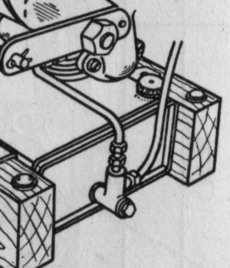
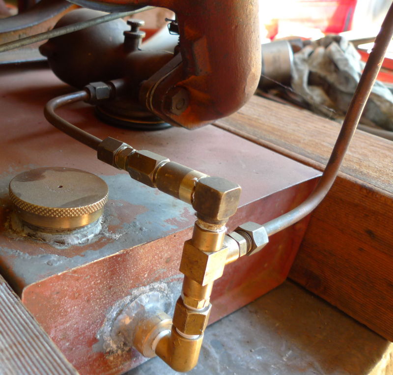
As we had none of the plumbing, and only the outline drawing from the Owner's Manual to go by, it took us some time to work out how it all worked. We finally determined that the missing three-way fitting on the fuel tank must contain two one-way ball bearing valves.
The pipework was scavenged from various tins, drawers and boxes in a shed, and made into a "T" with the leg of the "T" going to the pump. With the valves before and after the "T", fuel is drawn from the tank into the pump on the suction stroke and pushed up into the carburetter on the driving stroke.
The pump supplies far more fuel than the engine burns, so the carburetter bowl has an internal overflow. A pipe runs from the bottom of the bowl to the top, with small hole in the top of the pipe. When the fuel level reaches the top of the carburetter it flows into the pipe and down back into the fuel tank.
With the final assembly of the engine looming, we searched around for some suitable timber for a pair of skids. Some 4" square pine was located and found to be more then long enough. The mounting holes on the engine were measured and transferred to the skids, which were then drilled on the ancient belt-driven pedestal drill. We then rocked the engine sideways to slip the skids underneath, and found that the 4" width was only barely enough for the fuel tank to fit between while still clearing the inside edges of the flywheels. Evidently, 3x4 or 2x4 hardwood was used by the manufacturer.
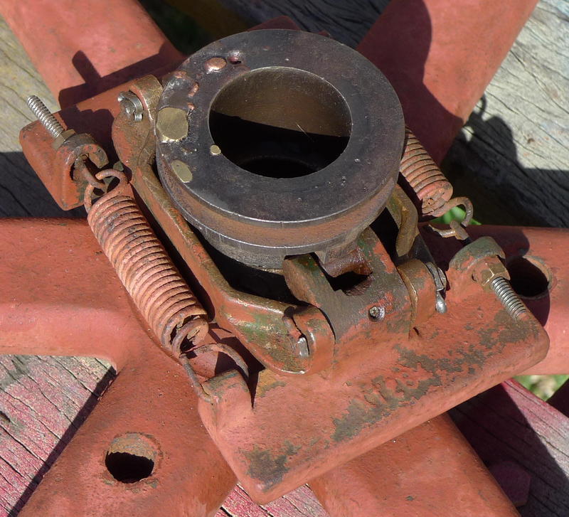
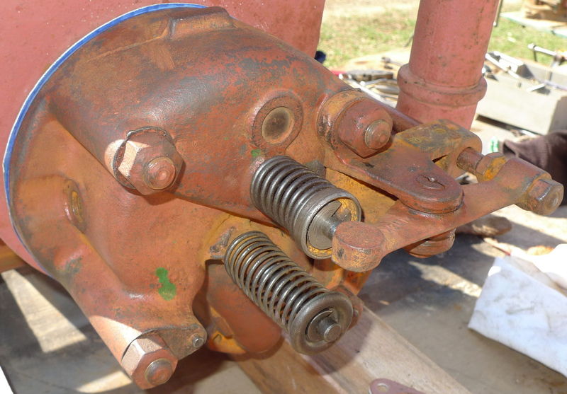
With the skids fitted, the repaired governor assembly and flywheel was replaced on the crankshaft and the governor rod and guides mounted to the side of the engine. The governor linkage is on the end of an arm which transforms the rotational rod movement into a push-pull movement across to the butterfly arm which returns to movement back into a rotation.
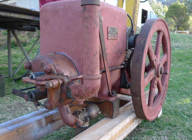
The arm to pushrod linkage has a brass assembly on the end which allows fine adjustment of the throw, and also includes a cam style lever with start and run positions. The backhoe was brought in, chains attached and the engine lowered to the ground. Being on the side of a hill, the front of the engine was propped up with a scrap of the skid timber to bring it more-or-less level. With the rebuilt fuel system being an unknown quantity, we decided to test the engine with a temporary fuel supply with adjustable flow. The tin can was hung nearby at approximately the level of the carburetor and the clear pipe attached to the intake. The height was adjusted so that fuel filled the tube without flooding the jet.
All the oiler holes were given a drink and we pulled the spark plug to confirm we were g etting a spark at the right time. Finally there were no more excuses, and we started cranking. Soon there was a cough and it stuttered into life, belching smoke and slowly wheezed to a halt. Encouraged with this success, we started playing with the fuel delivery system, needle valve and butterfly. Eventually a compromise was reached and the Sundial was chugging along happily, if a little rich.
We took a break to go to the Field Days at Gunnedah the next day, and to stop by the Gunnedah Rural Museum - which should really have been a day in itself.
Returning to the project we fitted the fuel tank, pipework and pump. Manually operating the pump resulted in an excess of fuel in the carburetor and overflow back into the tank, so we crossed our fingers and tried starting the engine again. After a little tweaking of the needle jet, it coughed to life, though there was a considerable amount of fuel splashing out around the hole where the carburetor bowl sits in the tank.
The engine still has some work to be done, as it is missing the cylinder oiler and could do with a paint job. Over the next few days we started it several times, to show to neighbors who dropped in or just to watch and listen to an old Sundial which had lain silent for nearly half a century.