
DIY Lathe DRO
Traditionally, Digital Readouts have been a feature of more expensive manual machine tools. They generally add at least a thousand dollars to a mill or lathe, and manufacturer/reseller supplied after-market kits may be much more. With the appearance in recent years of China-based online shops, the component parts of these DROs have become available directly to the consumer. This cuts the importer and reseller out of the chain, at the cost of the (sometimes questionable) value adding task of specifying the parts required for any given installation.
Fortunately, these DRO systems are electrically complete and only require physical installation and some minor configuration to be installed successfully on most standard machines. This article will show the fitting of a two axis glass scale DRO to a Herless CQ6230 lathe. This particular lathe is of the same series as the Grizzly 4002/4003 models commonly found in the USA.
Note that a third axis scale could be installed on the compound, with a 3-axis version of the DRO configured to sum the cross slide and compound scales with optional non-perpendicularity of the compound to compensate for a (for example) 30 degree angle.
Sizing The Scales
Both the saddle and the cross slide should be run to their maximum extents, making sure to remove any guards which may get in the way, including the tailstock. At some point you will want that extra travel, and not having to disassemble and then re-align the scales afterward will be worth the extra time and cost.
The bed worked out to be around 800mm and the cross slide 160mm. As the scales are available in 50mm increments, and 800mm scales were out of stock, the 850mm and 150mm scales were ordered. The 10mm sacrificed was placed at the rear of the travel, where it may or may not ever be noticed.
Positioning The Scales
 {.ephotor}
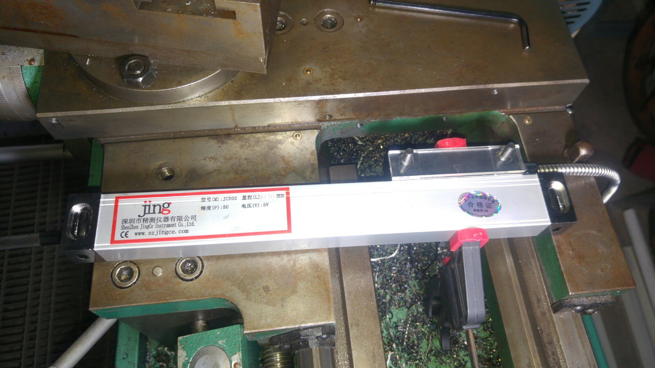
The scales consist of a long piece of aluminium channel with a glass scale fixed inside, and a short carriage with an optical read head inside the channel which slides along the length of the channel. The read head has sprung internal alignment bearings, but must be held firmly in alignment with the channel. It must move parallel along the channel in both axes and maintain a 1mm distance to prevent rubbing and sticking. The mounting holes in both the scale and read head allow precise alignment and packing shims should be used as necessary.
{.ephotor}
The scales consist of a long piece of aluminium channel with a glass scale fixed inside, and a short carriage with an optical read head inside the channel which slides along the length of the channel. The read head has sprung internal alignment bearings, but must be held firmly in alignment with the channel. It must move parallel along the channel in both axes and maintain a 1mm distance to prevent rubbing and sticking. The mounting holes in both the scale and read head allow precise alignment and packing shims should be used as necessary.
 {.ephotol}
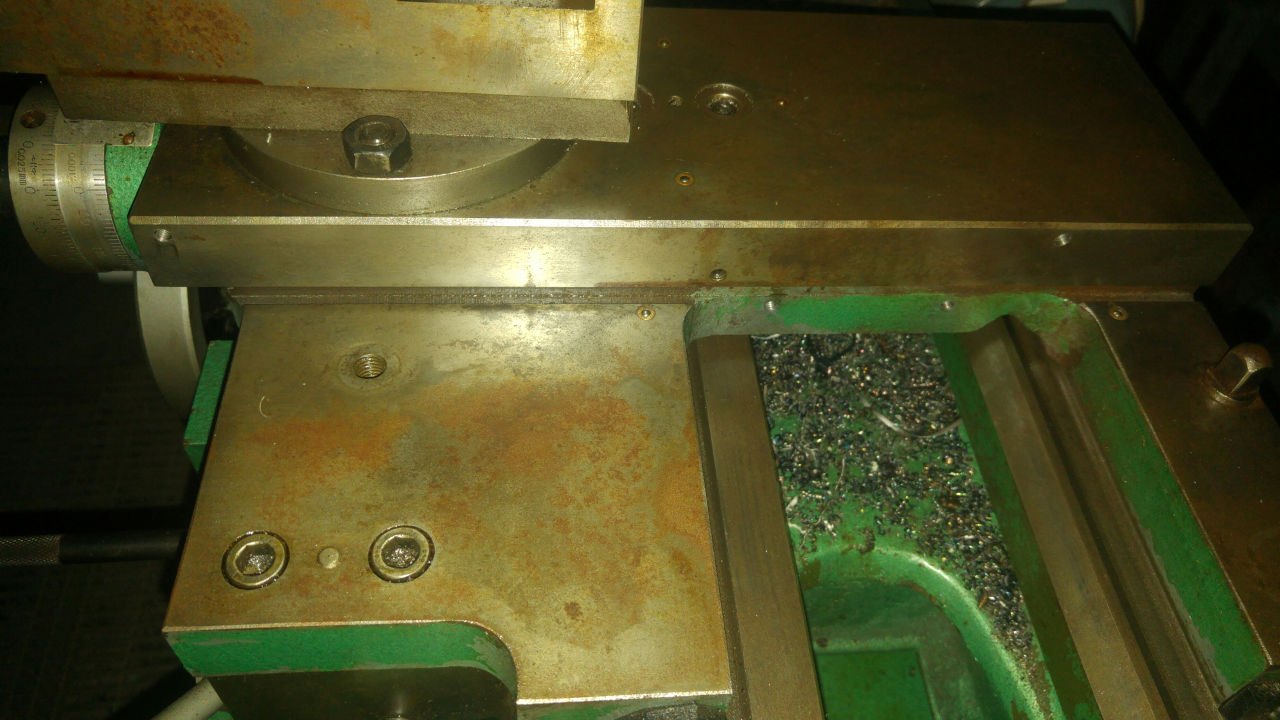
The cross slide read head attaches to the saddle, while the scale attaches to the cross slide. The CQ6230 uses tapered wedge gibbs, so the side of the cross slide only has the mostly unused locking grubscrew. The cable ties holding the read head to the scale were replace with slightly looser ones and the read head was moved along the scale to allow the assembly to be tested in several positions. Once an optimal location was determined - taking into account dovetails, gibb adjustment, material thickness, casting draught, etc - the cable ties were replaced with a small clamp and the positions of the scale mounting holes were marked. Packing out the read head was necessary, as the mounting surface on the saddle is recessed toward the headstock relative to the crosslide face. The saddle was moved to the end of the bed, with the tailstock removed, and the holes were drilled and tapped M5.
{.ephotol}
The cross slide read head attaches to the saddle, while the scale attaches to the cross slide. The CQ6230 uses tapered wedge gibbs, so the side of the cross slide only has the mostly unused locking grubscrew. The cable ties holding the read head to the scale were replace with slightly looser ones and the read head was moved along the scale to allow the assembly to be tested in several positions. Once an optimal location was determined - taking into account dovetails, gibb adjustment, material thickness, casting draught, etc - the cable ties were replaced with a small clamp and the positions of the scale mounting holes were marked. Packing out the read head was necessary, as the mounting surface on the saddle is recessed toward the headstock relative to the crosslide face. The saddle was moved to the end of the bed, with the tailstock removed, and the holes were drilled and tapped M5.
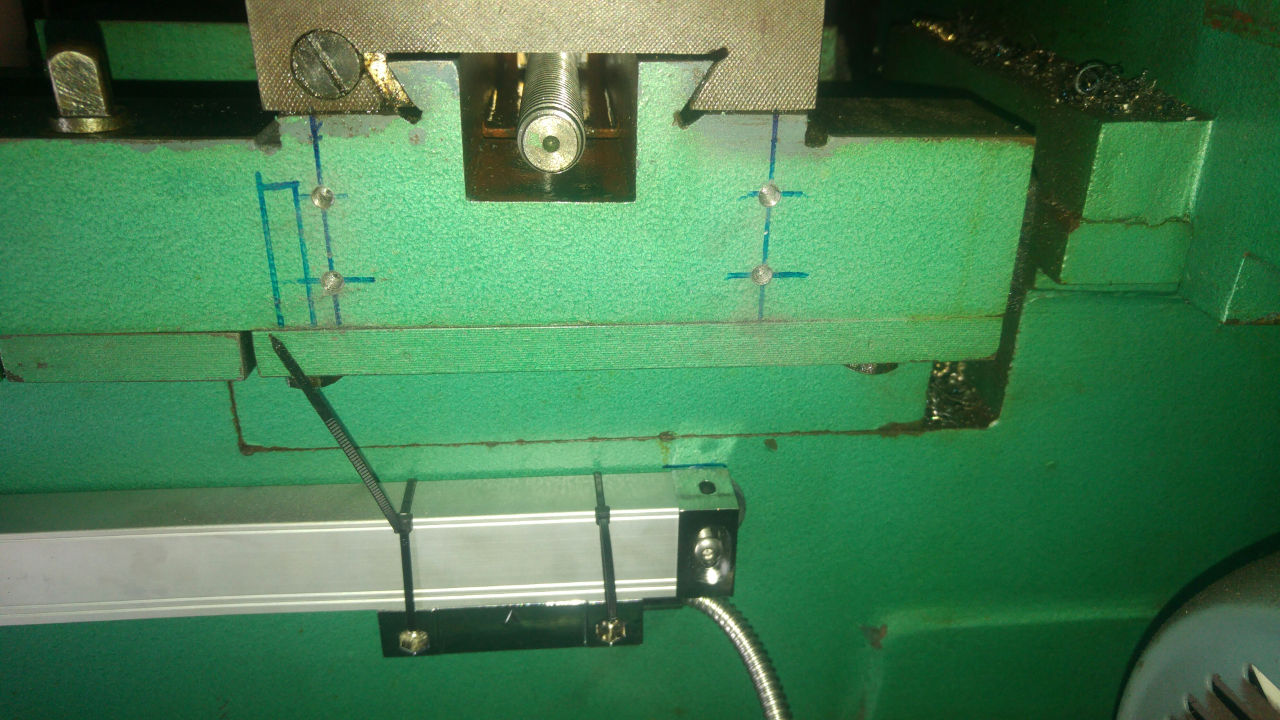
Positioning of the bed scale is similar to that of the crosslide, with the saddle moved to both extents and the scale positioned so that it is below the level of the removeable gap and clear of the splashguard. The rear of the saddle was marked out, avoiding the location of a nearby bolt, and mounting positions for a drop-plate marked out. Again, all the holes were drilled and tapped M5, with care taken to not drill too deep and damage the ways.
Mounting The Scales
 {.ephotol}
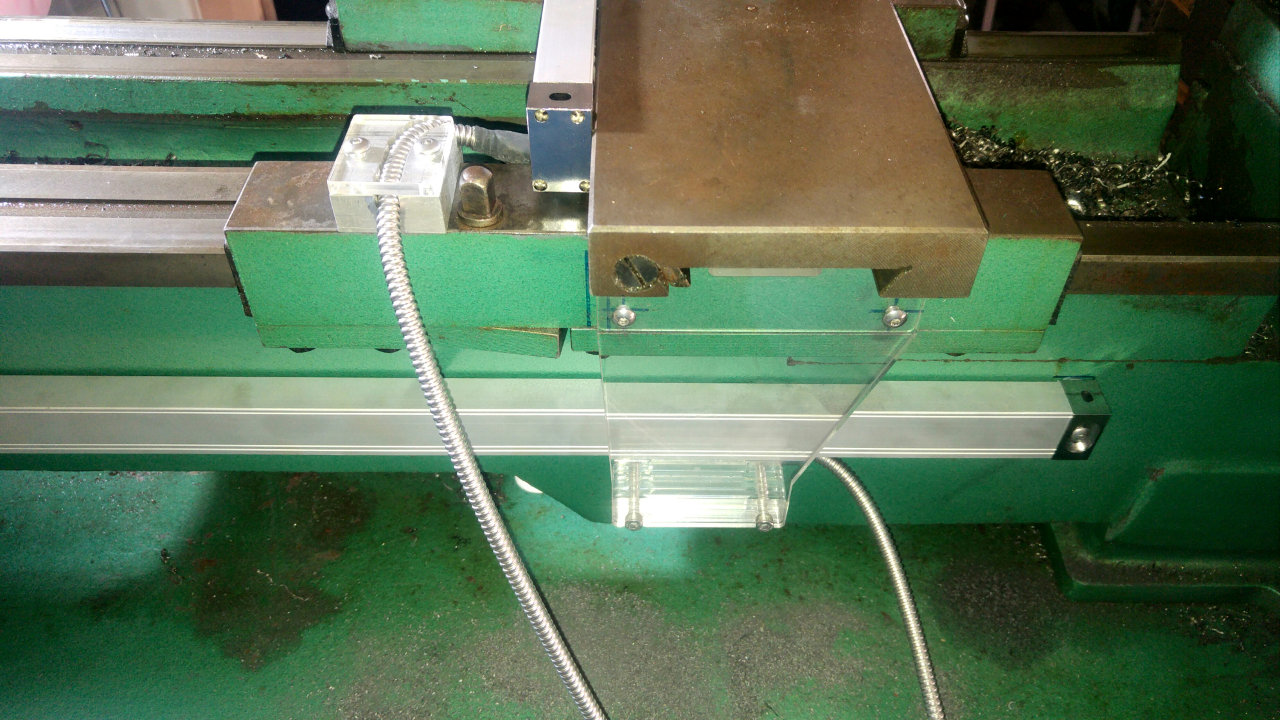
The cross slide scale mounts directly to the cross slide, so it's tapped M5 mounting holes were drilled out to 5mm. The assembly was then positioned and the read head bolted to the saddle with a packing piece. The scale was then bolted to the cross slide loosely and the clamp removed. An indicator was used to align the scale parrallel with the cross slide travel, with a 1mm gap maintained between the bottom of the scale and the top of the read head.
{.ephotol}
The cross slide scale mounts directly to the cross slide, so it's tapped M5 mounting holes were drilled out to 5mm. The assembly was then positioned and the read head bolted to the saddle with a packing piece. The scale was then bolted to the cross slide loosely and the clamp removed. An indicator was used to align the scale parrallel with the cross slide travel, with a 1mm gap maintained between the bottom of the scale and the top of the read head.
 {.ephotor}
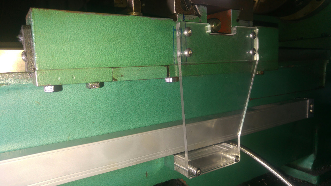
An oversight when aligning the bed scale necessitated that the drop plate between the saddle and the read head include a sideways offset so that the saddle could travel all the way to the headstock. A number of packing pieces of various thicknesses was also cut, and the read head bolted to the drop plate. The scale was then indicated parallel with the ways.
{.ephotor}
An oversight when aligning the bed scale necessitated that the drop plate between the saddle and the read head include a sideways offset so that the saddle could travel all the way to the headstock. A number of packing pieces of various thicknesses was also cut, and the read head bolted to the drop plate. The scale was then indicated parallel with the ways.
Cable Management
 {.ephotol}
This model of DRO comes with flexible metal sheaths protecting the scale cables and has some strain relief built into the ends. It is a good idea, however, to provide additional support. The cross slide scale, read head and cable is also vulnerable to the tailstock being run up to the crosslide. Some people have chosen to mill a channel across the rear of the saddle for the cable to run through. In this case, about 75mm of tailstock travel has been sacrificed with the installation of a bracket which routes the cable over the rear of the saddle, provides strain releif and also a positive stop for the tailstock.
{.ephotol}
This model of DRO comes with flexible metal sheaths protecting the scale cables and has some strain relief built into the ends. It is a good idea, however, to provide additional support. The cross slide scale, read head and cable is also vulnerable to the tailstock being run up to the crosslide. Some people have chosen to mill a channel across the rear of the saddle for the cable to run through. In this case, about 75mm of tailstock travel has been sacrificed with the installation of a bracket which routes the cable over the rear of the saddle, provides strain releif and also a positive stop for the tailstock.
Display
 {.ephotor}
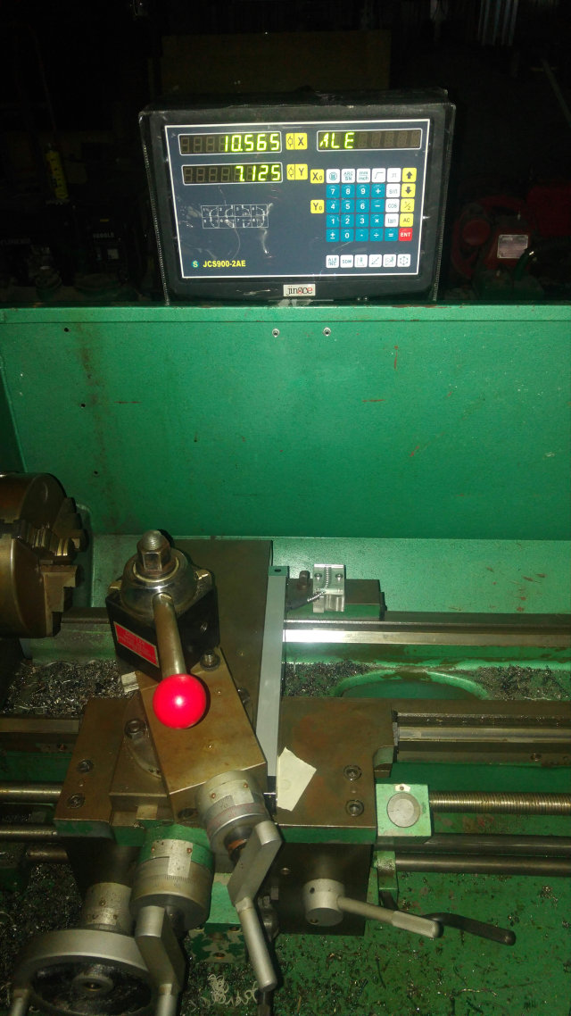
Once again, most of the mounting hardware was discarded, and the display was mounted on the splashguard. The two cables were routed under the bottom of the splashguard and screwed to the back of the display. When first powered on the cross slide movement was correct, however the saddle movement was in the reverse direction to my preference. This was easily rectified with a setting on the display to reverse that scale. The final change was to configure the display for "Lathe" mode, which allows the Y axis to be switched between radius and diameter modes with a single button.
{.ephotor}
Once again, most of the mounting hardware was discarded, and the display was mounted on the splashguard. The two cables were routed under the bottom of the splashguard and screwed to the back of the display. When first powered on the cross slide movement was correct, however the saddle movement was in the reverse direction to my preference. This was easily rectified with a setting on the display to reverse that scale. The final change was to configure the display for "Lathe" mode, which allows the Y axis to be switched between radius and diameter modes with a single button.
Resolution
The scales have a resolution of 0.005mm or 0.0002", which is somewhat in excess of many people's machining skills. Some choose to disable the last decimal digit of the display, as it is only a distraction to the eye.